
The 6th International Conference on Mining Science & Technology
Finite element analysis of wear for centrifugal slurry pump
Dong Xinga, Zhang Hai-lua, Wang Xin-yongb,*
Institute of Mechanical Engineering, Heilongjiang Institute of Science and Technology, Harbin 150027, China
College of Mechanical and Electrical Engineering, China University of Mining and Technology, Xuzhou 221116, China
Abstract
By applying theory of liquid-solid two-phase flow, the location and process of wear on pump are analyzed. The results are consistent with the real wear situation. On this basic, base on the geometry non-linear theory and material non-linear theory, the wear process on flow components was simulated by ANSYS. The simulation results showed that there will be pits on the surface of flow components due to the impacting of coal particles with certain diameter, shape, impacting velocity and invasive angle; and the largest Von Mises stress will be at the pits. The distortion degree of pits and the largest Von Mises stress will increase with the increasing of coal particle diameter, impacting velocity and invasive angle, and with the decreasing of tip angle. There will be some accumulation at the front-end of impacting when the invasive angle is small.
Keywords: centrifugal pump; slurry pump; wear; finite element
1. Introduction
In recent years, with unceasingly increase of quantity of cleaning and processing coal, the
development of coal preparation process with dense medium in the coal preparation plant has been
promoted. In dense medium cyclone coal preparation, centrifugal slurry pump must always be used
for feeding materials
two-phase slurry which is a mixture of water, coal, gangue and magnet powdered ore. Because the
working condition is very bad, serious partial wear to the flow components of pump is caused,
which not only reduces the operational reliability of pump, but also reduces the service life of
pump[2-4]. Therefore, besides energy saving and high efficiency, higher requirement to the
operational reliability of pump is also proposed at coal preparation plants. There will be great
significance for safe production to study the wear location and wear process of centrifugal slurry
pump used in dense medium cyclone, and to reduce the wear degree of the slurry pump.
2. Wear location and wear process
- Wearlocation
- Wear location onimpeller
The main location of wear on impeller is in turn the impeller vane outlet and inlet, the intersect
point of the vane inlet with rear cover plate, internal surface of rear cover plate, and the
middle of vane[5-9]. In the flow channel of axial surface of impeller, when solid particles enter
the flow channel, the direction of motion of the particles from axial turns to the radial
direction. Due to centrifugal force, the majority of solid particles are transferred to the rear
cover plate, which results in the degree of wear at the rear cover plate larger than that at the
front cover plate. Especially, the wear at the intersect point of vane inlet with rear cover plate
is the most serious. In the plane flow channel of impeller, small solid particles have good
characteristics of following with fluids due to their small inertia. Therefore, in the inlet of
impeller vane, particles get into the flow channel of impeller along the direction which
approaches the liquid flow angle at vane inlet with low impacting velocity and light wear on the
vane inlet edge. In the flow channel of impeller, particles move along the vane working surface
with a curvature of motion trace close to the vane type curvature, and their radial velocity and
outlet liquid flow angle are small. As a result, wear on the outlet edge caused by small particles
is more serious than that on the working surface. Large particles have bad characteristics of
following with fluids due to their big inertia. Therefore, in the vane inlet, particles get into
the flow channel of impeller with direction different from the liquid flow angle of vane inlet, so
that many large particles impact on the vane inlet edge, and some of the big particles are pushed
to the back of the vane, which results in wear on the vane inlet edge and the back of the vane
outlet. In the flow channel of impeller, large particles loss momentum after impacting, there
will exist three different situations: the first one is that the reflect velocity of particle is
so large that the particle flows straightway out of impeller after impacting, without impact with
vane again; the second one is that the reflect velocity of particle is relatively large, so that
the particle does not flow out of the vane outlet immediately, and impacts with the vane working
surface again (may be more than two times), which produces wear on the middle part and the outlet
of vane working surface; the third one is that the reflect velocity of particle is so small or
zero after impacting that particles will not bounce off from the vane surface, but rolls or glides
along the vane surface, so that wear on the middle part and the outlet of vane working surface is
produced.
- Location of wear in dischargechamber
The main locations of wear in the discharge chamber are in turn the Ⅷ cross section, pump tongue,
the I cross section and sidewall[8-10]. For small solid particle with small outlet liquid flow
angle out of impeller, its motion trace is approximately a concentric circle in the discharge
chamber. It forms circulation flow through the pump tongue, then the majority of solid particles
are returned to the discharge chamber. Therefore, uniform wear on the discharge chamber sidewall
and outer wall is produced. For large solid particles with large outlet liquid flow angle out of
impeller, particles will impact on the outer wall of discharge chamber and move to diffusion tube
along outer wall, and serious impact will be produced on the pump tongue. Therefore, it creates
wear on the outer wall of discharge chamber and the pump tongue.
For example, a centrifugal slurry pump is used to supply material for dense medium cyclone in a
coal preparation plant. There are three situations of wear on the impeller and discharge chamber.
The first is wear on the impeller vane working surface outlet and back outlet, which makes the
outlet edge became thin concave arc, and presents obvious trench at the outlet edge of working
surface. Four outlet edges of the five vanes largely pell off because of wear (Figure 1). The
second is that the inlet diameter of impeller becomes larger because of wear on the intersect
point of the impeller vane inlet edge with the rear cover plate. The third is the VIII cross
section region of the discharge chamber appears obviously linearity trench due to wear, the pump
tongue becomes non-arc, and its length gets shorter (Figure 2).
- Wearprocess
There are three stages in the process of wear on flow components of the centrifugal slurry pump:
The first is saturation wear stage: the flow components of the centrifugal slurry pump are
founded; there is some roughness on the surface of components; the surface becomes smooth due to
wear caused by particles after first running of the pump; and the process of wear gradually
becomes steady from being faster at the beginning.
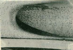
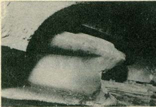
Fig. 1. Wear on outlet edge of the impeller vane working surface Fig. 2. Wear on VIII cross section of the discharge chamber and pump tongue
The second is steady wear stage: wear is relatively steady because the surface of flow components
has been worn glossy at the first stage; this stage lasts for a longer time; it is the best stage
for pump running.
The third is sharp wear stage: with long time of running, the size and angle of components may
largely depart from designed hydraulic working conditions due to wear; particle impacting and
medium flow separation vortex are intensified; the speed of wear increases sharply; the pump may
not be able to run properly, and there exist hidden accidents.
In the above three stages of wear process, the main wear is micro-cutting wear when particles
impact with small angle, while distortion wear is the main one when particles impact with large
angle. In this paper, wear process caused by particle impacting is analyzed by numerical
simulation method.
3. Basic model and calculation method
- Geometrymodel
Geometry model adopts two-dimension plane model. Solid particles are chosen to simulate coal
particles, supposing the shape of coal particle to be circle and equilateral triangle. The
diameters of coal particles are 2.5mm and 10mm respectively. Because the character size of flow
components is much larger than the size of coal particles, the surface of flow components impacted
by coal particles is assumed as ideal plane. Taking a rectangle area as target, both of the width
and height of the rectangle are 100mm. Due to the axial symmetry of physical model, a half of the
model is analyzed (Figure 3). When coal particles impact target by certain invasion angle, the
entire model is used.
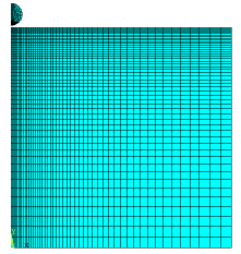
Fig. 3. Finite element model
- Finite elementmodel
In finite element model, both coal particles and target adopt two-dimension axial symmetry entity
whose element number is 162. Manual grid partition is adopted. The grid shape for coal particles
and target are rectangle. Local grid encryption is used at some local areas where coal particles
impact the target, getting 181 elements with 209 nodes on coal particle, while 5625 elements with
5776 nodes on target (Figure 3). The boundary condition of model: coal particles impact on the top
boundary of target along the direction of minus y. All nodes on the top boundary of target have
the freedom in both x and y, without restriction in displacement. All nodes on the symmetry axis
of target have no displacement in x direction. That is, all nodes on the symmetry axis have
restricted displacement in x direction. The displacement is zero in both x direction and y
direction for all nodes on the bottom boundary and right boundary of target model. That is, the
displacement is restricted for all nodes in these two boundaries in both x direction and y
direction.
- Contactmodel
In ANSYS/LS-DYNA, the two-dimensional Lagrange law is used for analyzing; and dynamic contact
symmetry penalty-function method is adopted for contact-impact finite element numerical value
calculation; contact type chooses single contact arithmetic[11] which is
COTACT_2D_AUTOMATIC_SINGLE_ SURFACE. The contacting dynamics friction coefficient of coal
particles with component surface is 0.1, and static friction coefficient is 0.15.
- Constitutivemodel
Target material is high chromium cast iron. The material constitutive model adopts Bilinear
Isotropic hardening model which satisfies Von Mises yield rule. Elasticity module of the model
parameter is 170GPa, the density is 7810kg/m3, Poisson ratio is 0.3, yield limit is 396MPa, and
the tangent module is 75GPa. Elasticity module of coal particle is 1.4GPa, Poisson ratio is 0.3,
and density is 1500kg/m3.
- Calculationmethod
Central differential time integral explicit arithmetic is used. Load mode of model adopts velocity
load of coal particles. Considering the actual impacting phenomenon of the coal particles in the
pump, the load velocity of coal particles are defined as 3m/s and 5m/s, and the invasion angle is
90° and 15°, respectively. The artificial volume viscosity is 1.0, time step factor is 0.9, and
calculation time is 3×10⁻⁶ s and 5×10⁻⁵ s, respectively.
2. Results and analysis
- Influence of coal particlediameter
Figure 4 and 5 give the distortion in the material surface and the biggest Von Mises stress after
loading by a sphere coal particle, with diameter d of 2.5mm and 10mm and velocity v of 3m/s,
vertically impacts the material surface. It can be seen from Figure 4 (a) and 4 (b), there is
obvious pit resulting from coal particles impacting on the material surface, and the depth and
width of the pit increase along with coal particle diameter. It can be seen from Figure 5 (a) and
5 (b), the biggest Von Mises stress appears in the pit, and it increases along with the coal
particle diameter. When the diameter is 10mm, the biggest Von Mises stress is 48.3MPa. Within
material, distribution of Von Mises stress changes from approximately semicircle to circular with
increase in depth. According to Mises yield rule, when the biggest Von Mises stress is larger
than the yield stress of material, plastic flow will occur in this area first. Because the yield
stress of high chromium cast iron is as high as 396MPa, the material has elastic deformation only.
However, due to repeatedly impacting of coal particles in the centrifugal slurry pump for a long
time, fatigue flake of the material occurs, and wear will happen.
- Influence of coal particlevelocity
Fig.6 shows the distortion in the material surface and the biggest Von Mises stress produced by
coal particle, diameter 2.5mm and velocity 5m/s, vertically impacting on the surface of material.
From Figure 4 (a), Figure 5 (a) and Figure 6 (a), 6 (b), it can be obviously seen that pit is
produced by coal particle impacting on the material surface, and the biggest Von Mises stress
appears in the pit. The depth and width of the pit and the biggest Von Mises stress increase along
with the impacting speed of coal particles. When the impacting velocity is 5m/s, the biggest Von
Mises stress is 79.3MPa.
Fig. 4. Distortion on material surface by different diameters of coal particles (a) d=2.5mm, v=3m/s (b) d=10mm, v=3m/s
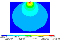
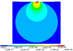
Fig. 5. The biggest Von Mises stress by different diameters of coal particles (unit: Pa) (a) d=2.5mm, v=3m/s; (b) d=10mm, v=3m/s
- Influence of coal particleshape
Fig.7 gives the distortion on the material surface and the biggest Von Mises stress resulted from
vertically impacting of angular coal particles with taper angle of 60˚ and impacting velocity 3m/s.
From Figure 4 (a), Figure 5
(a) and Figure 7 (a), 7 (b), it can be seen that the biggest depth produced by angular particles
with a taper angle of 60˚ is bigger than that produced by sphere particles with diameter of 2.5mm,
and microscopic zigzag distortion is produced by angular coal particles impacting on the material
surface. As a result of stress concentration at the zigzag root, the biggest Von Mises stress is
obviously bigger than that produced by sphere particles with diameter of 2.5mm. Therefore, the
shape of coal particle is also an important factor for wearing.
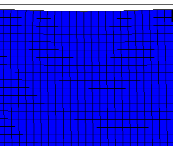
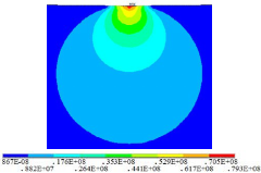
Fig. 6. The distortion and the biggest Von Mises stress by coal particles impacting on material surface (a) Distortion; (b) The biggest Von Mises stress (unit: Pa)
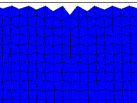
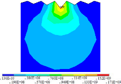
Fig. 7 The distortion and the biggest Von Mises stress by coal particles impacting on material surface (a) Distortion; (b) The biggest Von Mises stress (unit: Pa)
- Influence of invasion angle of coalparticles
Fig.8 gives the distortion which produces in the material surface and the biggest Von Mises stress
produced by sphere coal particle with diameter 2.5mm and velocity 3m/s impacting on the material
surface at an invasion angle of 15˚. It can be seen from Figure 4 (a), Figure 5 (a) and Figure 8
(a), 8 (b).
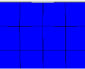
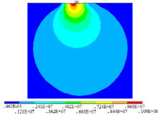 Fig. 8. Distortion and the biggest Von Mises stress by coal particles impacting on material surface at invasion angle of 15˚ (a) Distortion; (b)The biggest Von Mises stress (unit: Pa)
The distortion depth and the biggest Von Mises stress produced at the invasion angle of 15˚ is
smaller than which produced by vertical impacting. And micro cutting is obvious when coal
particles impact the material surface with an angle. There will be pushing phenomenon at the
front-end of material surface, resulting in microscopic accumulation.
The data of coal particles impacting on material surface are given in Table 1.
Table 1. The data of coal particles impacting on material surface
| Coal particle diameter (mm) | Coal angle (°) | particle Impacting
velocity (m/s) |
Impacting angle (°) | Depth of pit (μm) | Half width of pit (μm) | Biggest Von Mises stress (MPa) |
| 2.5 | 3 | 90 | 0.18766 | 3.65852 | 20.5 | |
| 10 | 3 | 90 | 0.88743 | 26.83523 | 48.3 | |
| 2.5 | 5 | 90 | 0.31746 | 7.93654 | 79.3 | |
| 60 | 3 | 90 | 0.39953 | 4.48652 | 171 | |
| 2.5 | 3 | 15 | 0.00213 | 0.15874 | 10.9 | |
|
|
5. Conclusion
The main locations of wear on the impeller of centrifugal slurry pump are in turn the impeller
vane outlet and inlet, the intersect point of vane inlet with the rear cover plate, internal
surface of rear cover plate, the middle of vane. And the main locations of wear in discharge
chamber are in turn the Ⅷ cross section, pump tongue, the I crosssection and The process of
wear consists of saturation wear, steady wear and sharp wear.
Adopting dynamic contact symmetry penalty-function method as contact-impact finite element
numerical value calculation method corresponds with the contact characteristics of the coal
particles impacting on the flow componentsof centrifugal slurry pump, and good numerical
simulation result could be
Pits will be produced when coal particles impacting on the surface of flow components. The biggest
Von Mises stress appears at the pit. The distortion degree and the biggest Von Mises stress will
increase along with the coal particle diameter, the velocity and the invasion angle, and increase
with reducing of the taper angle of coal particle.
References
[1] H. Q. Zhang, Gravity Concentration. Beijing: China Coal Industry Publishing House. 1987. [2] A. M. Tian, H. Y. Xu, X. W. Luo, The research on abrasion of the impellers of centrifugal slurry pump. Coal Mine Machinery. 1 (1998) 71-73. [3] H. Y. Jiang, R. Q. Huang, Z. L. Lv, Wear of the parts of slurry pump and selection of materials. Water Conservancy & Electric Power Machinery. 24 (2002) 10-14. [4] Q. Z. Zhang, Abrasion Analysis of centrifugal slurry pump and selection of materials. Pump Technology. 4 (2008) 33-34. [5] H. Y. Xu, D. R. Lu, The research on abrasion of the impellers of centrifugal slurry pump. Tribology. 18 (1998) 248-253. [6] B. H. Zhou, H. S. Wang, Anaiysis wear of slurry pump and study of pumt design. Hydraulic Coal Mining & Pipeline Transportation. 2 (2000) 91-92. [7] S. Li, Abrasion mechanism of vanes with ADI in slurry pump. Fluid Machinery. 28 (2000) 5-8. [8] H. Wang, Wear analysis and study of the impellers of centrifugal slurry pump. Hydraulic Coal Mining & Pipeline Transportation. 2 (1996) 17-20.